Tuesday, April 19, 2011

week 12 and 13 - final project part 3

I combined 2 weeks' blog together because the final on other courses.


As I indicated in week 11, we did not provide enough effective research, so our project became "developing on the go".


The concept now is basically developed, but applying into real practice, we need more research and test. we have to experience the hardcore feeling, and then come the real development.


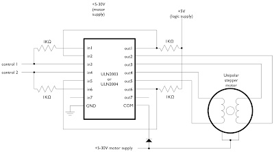
First, we only have the stepper motor, but we need a chip called ULN2003 to drive it! So, Lee's again. 


After we got the ULN2003 chip, we assembled the first prototype circuit that only drives the stepper motor.

Now we come to the Second problem, the mini Arduino board does not have a voltage regulator, so if we only use the 9v battery, then the accelerometer will be burned...

So, we need the the alternative, which is the original sized Arduino board, and a bigger container...


After this, is the crazy time consuming coding part, personally, I am dead on this process.


week 11 - final project part 2

For this week, it is considerably busy because there are final actions we need to work on and there are not much  time we could work together. 

As a result, we deployed our survey to the nearby friends and I got the most equipment supply from Lee's Electronics.

The feedback is very useful, but we did not consider enough, which cause large amount of trouble later.

These are some equipment we got.
accelerometer

stepper motor (precise control)

mini Arduino Pro (minimize the size of the bottom)

and our ideal sized bottom


week 10 - final project part1- ideation

For this week, based on our original research plan, we deliver 2 ideas to the Prof and TA, and we will pick the one they thinks have most potential.


First, the Smart Goblet.


We want the person who is holding the glass can automatically place back to the standing position without actually seeing the glass is tilting. It is more like react intuitively.


For the material, we will use: Ingot(9V bettery), a goblet, LiliPad Arduino board, accelerometer, 360 degree SEVO motor(or stepper motor), the base, axle.


We started research this idea by doing a survey:


First, how does people hold the goblet usually?
Second, did they pay enough attention when they tilt the goblet un-purposely?
Third, what kind of simulation may “force” the user to balance the goblet intuitively in a mild way?
Fourth, is the embodiment design we have doable?
Fifth, is this solution towards this problem could cause other problems?


Second, the Space Travel Simulation Pad.

We want the participant feel the virtual space of being in the galaxy and have the direction and speed control of the environment.


For the material, we will use: Pad materials(wood shield), vibration motor, pressure sensor, arduino board, projector.


Our research is driven by several questions:

First, how hard a person’s step usually? (It’s vary according to their weight)
Second, when do they want to turn to different direction?
Third, When do they want to step harder?
Fourth,  is the embodiment design we have it’s doable?
Fifth, is there other cause-effect problems?


This idea also drives us some critical thinkings, how does people think they will move in space?(step or tilt as simulation?). we will require another survey to decide the direction of our project development.


However, after communicate with both Prof and TA, we finally decide to take the goblet idea for further development. Time is tight,other 3 courses' final action is also on the way.

week 9 - failed plans for the final project


Research

There are mainly 3 goals we need to achieve in this project.

First, our design needs to be tech adapts human’s behavior.
Second, the interactions need to be based on human intuitions, which means the reactions from our simulations will be the same or at least similar as it is used to be.
Third, the smart part, of sensitivity, we need to set in degree responding, which means, a sensor with only one trigger will not work, we need sensors like accelerometer or multiple sensors to achieve degrees of responds.


However, due to we were lack of communication, we delivered something completely irrelevant to the requirement, which is below.(A wine bottle could detect how much liquid left inside the bottle.)
This idea did every check box we planed, but we totally ignored the most important factor: Embodiment!


Since there are not much interaction that could intuitively remind people when they are acting,  we have to abandon this idea, and develop new plans next week.

Wednesday, March 16, 2011

Week 8 - Wearable Computing II

This week's post will be more focused on our technical term.


CONCEPT
We design this particular piece for police officers. In order for police work
and manage easily when they met the traffic jam or the traffic accidents at
night time.


HOW IT WORKS
The accelerometer reads the date from the participant’s hand by their
speed of the movement, then sends the data to LED lights (output). the
LED lights read the signal from the accelerometer and response with
different speed of blinking.


our final circuit digram:


CULTURE/SOCIAL INTERACTION

We develop this project to help the Police officers work better and efficient
at the night time. In addition, we can easily to understand what the Police
officers’ meaning at night ( dark envinonment ) through their body language.

HUMAN INTERACTION

Based on our project, police officer can interact and commuicate with
people easily by using the LED signal through the Arduino. This particular
piece is very easy to use. By daily movement and their special hand
gesture, the speed of the LED lights will according to those hand.


Work progress:
Many many wires

First test:


The base sequence of the LEDs:

The finalized sequence of the LEDs. (airport directing signal sequence)


The last step, after we adjust the reading value from the Accelerometer, we give 3 level of speed to the sequence of the light.


When the user does not move, the "Z" parameter value below 350, the speed is on the fastest mode.
When the user start moving the arm, the "Z" parameter value above 350 and below 460, the speed is on the normal speed mode.
When the user moves the arm really really fast, the "Z" parameter value above 460, the speed is on the slowest mode.

By using this setting, when the police waving his hand slowly, the light speed is faster, this behavior will save energy from the police. On the opposite side, if the police waves the arm too fast, the driver on the other side of the street will still be able to read the signal because it lights slower.

Week 7 - Wearable Computing I

The original idea is a bit tooooo complex. It is a police jacket that use LEDs to manage the traffic.  Our concept is to inter-grade technology with a police jacket to  make the police's life easier when they are doing their job.


As illustrated above, we will use many components to achieve the interactive jacket below.


The form got inspired by Pillobot : The softer Side of Technology and The climate dress


The LED sequence got inspired by Airport directing signal, which is the most efficient and understandable signal.

However, after we got some feedback from the professor, we decide to limited our goal , which means we are only going to focus on the LEDs functionality as the target for SKETCH 2.


Week 6 - Soft Circuit

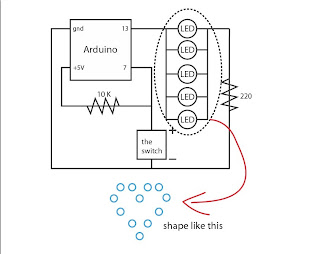
This is the basic circuit we got from the lab. In our idea, we parallel connect more LEDs to form a shape, and we install it on one jecket.


Our idea is to let the LED light turn on in a constant low speed while the jacket button is not press, and when it is press, the LED light is light uo in a constant but a faster speed. So the jacket button is the switch in this case. 
In detail, the jacket has two buttons which indicates the "+" and "-". The LED lights are paced on the lift side of the jacket so that the whole circuit should like the image showed below. The + button(which connects to Pin 7 on the Arduino Board) we placed on the right side and with a 10K resistor (which connects to 5v). 

The problem we faced for the assignment 2 is that we did not  find a good way to weave the conductive thread into the jacket, the connection is very loose. In the end, there are a few light does not light on after active the circuit.
We need to improve the weaving technique in the future assignment.